
Inverters used in industrial motor drives, renewable energy systems, and energy storage equipment must convert electrical power efficiently while maintaining reliable operation under changing loads. Insulated-gate bipolar transistors (IGBTs) remain important switching devices in many medium-power and high-power applications. Their performance depends not only on the semiconductor module but also on switching control, circuit layout, thermal management, and fault protection. Understanding these factors helps engineers balance conversion efficiency, electromagnetic compatibility, and equipment reliability.
Understanding Switching Losses in an IGBT Switch

An IGBT switch experiences conduction losses while carrying current and switching losses during turn-on and turn-off transitions. Conduction losses are influenced by collector current, junction temperature, and the device’s collector-emitter saturation voltage. Switching losses arise because voltage and current overlap temporarily as the device changes state.
These losses affect inverter efficiency and cooling requirements. Switching losses generally increase with switching frequency, making them particularly important when engineers select operating frequencies for motor drives and power conversion systems. Actual losses depend on the device, current, DC-link voltage, gate resistance, temperature, and circuit parasitics.
Engineers can estimate switching energy from device datasheets and operating conditions, then validate their calculations through testing. Reducing losses should not be pursued in isolation: a design that minimizes switching energy but produces excessive voltage overshoot or electromagnetic interference may require additional protection and filtering.
Switching Speed: Balancing Efficiency and Electrical Stress
The speed of an IGBT’s transition is strongly affected by the gate current used to charge and discharge its gate capacitance. A gate resistor helps control this current and therefore influences switching time, voltage rise, current fall, and transient behavior.
Lower gate resistance can accelerate switching and reduce switching losses. However, faster transitions may increase voltage overshoot caused by stray inductance, intensify electromagnetic interference, and aggravate oscillations. Higher resistance can moderate these effects but may increase switching losses and device heating.
A properly selected IGBT gate driver supplies the required gate voltage and current while maintaining controlled transitions. Engineers should evaluate turn-on and turn-off resistance separately where the circuit permits, since the two transitions have different loss and stress characteristics. Double-pulse testing can help verify switching energy, overshoot, and waveform stability under representative operating conditions.
Circuit layout also matters. Short gate-drive loops, appropriate isolation, carefully managed DC-link inductance, and sound grounding practices help limit parasitic effects. These measures become especially important in high-current power assemblies, where even small stray inductances can contribute to significant transient voltages.
Protection Against Short Circuits and Undervoltage
Fast switching cannot compensate for inadequate fault protection. Short circuits can produce excessive current and rapid heating, while abrupt turn-off under fault conditions can create dangerous voltage overshoot. Protection must therefore detect abnormal operating conditions and respond within the device’s safe operating limits.
Undervoltage lockout (UVLO) prevents operation when the gate-drive supply falls below an acceptable threshold. Insufficient gate voltage can increase conduction losses and expose the semiconductor to damaging thermal stress. Short-circuit protection detects a fault and initiates a controlled response; soft shutdown can reduce turn-off stress compared with an unnecessarily abrupt interruption.
Protection thresholds, detection delays, and shutdown behavior must be coordinated with the selected module’s short-circuit withstand time. Engineers should also consider fault reporting, noise immunity, and the possibility of false triggering. Datasheet limits and application testing are essential because protection features do not guarantee survival under every fault condition.
Selecting a Gate-Drive Solution for Industrial Inverters
Selecting an IGBT gate driver for an industrial inverter involves more than checking peak current. Engineers should confirm compatibility with the module’s voltage rating, recommended gate voltages, required switching frequency, isolation arrangement, and intended inverter topology. Output power, thermal conditions, interface requirements, and fault-management functions also affect integration.
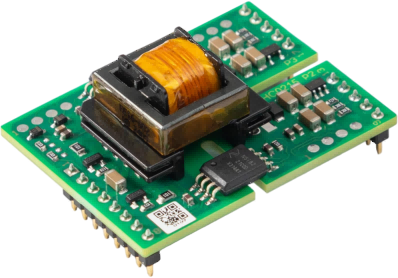
Firstack specializes in power semiconductor driver development, providing gate driver cores for IGBT-based power conversion systems across industrial applications. Its 2FHC0215C gate-driver family is designed for 1700 V IGBT applications and supports multi-level topology. The product information specifies dual-channel operation, a 15 A peak gate current, and up to 2 W output power per channel at maximum ambient temperature.
The documented protection functions include undervoltage protection, short-circuit protection with soft shutdown, and active clamping. The driver core is designed for IGBT power modules rated up to 900 A and 1700 V, with a 15 V turn-on gate voltage. Its stated operating ambient temperature range is −40°C to 85°C.
These specifications provide a starting point for evaluating the 2FHC0215C in inverter designs. Final selection still requires checking the exact model variant, electrical interface, gate-voltage requirements, switching-frequency limits, and application documentation against the intended hardware.
Validation: Connecting Efficiency with Reliability
Before production, engineers should validate IGBT switch performance and switching waveforms across expected load and temperature ranges. Measurements should include switching energy, peak collector-emitter voltage, gate voltage, current behavior, and thermal performance. Tests should also examine startup, shutdown, undervoltage events, and short-circuit response under controlled laboratory conditions.
Simulation can identify likely problems early, but it cannot fully replace hardware validation. Parasitic inductance, component tolerances, layout differences, and measurement-probe effects may alter observed results. A repeatable test procedure helps engineering teams compare design revisions and confirm that efficiency improvements do not compromise protection margins.
Building a Better Inverter Design
Reliable inverter performance depends on treating IGBT switch losses, transition speed, and protection as interconnected design priorities. Engineers who assess semiconductor characteristics, gate-drive behavior, circuit parasitics, and fault response together can make more informed trade-offs between efficiency and durability. Firstack‘s 2FHC0215C provides documented drive and protection capabilities for relevant high-voltage applications, while careful compatibility checks and practical testing remain essential to a successful design. An IGBT gate driver should always be evaluated against the requirements of the complete inverter system.
